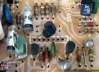
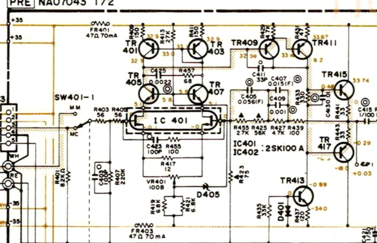
ja man borde kunna kolla det i schemat. vart sitter dom där? riia? pre?
sparar du bilden på japs sidan å zoomar in lite ser du hur han satt i sina k30 och kan gå efter det åxå. givetvis kolla mot schemat åxå.
edit: aha är det IC401,402 i försteget?
jag tror att vilka du än väljer så måste dom vara matchade. och proceduren borde ju vara samma som på k117 där han beskriver lite hur man kan göra.
Jag samlar upp all info här på sidan så blir det lite lättare att reda ut detta
"I would replace them with (2) 2SK117 jfets. You will have to match them. You can just match them for Idss. Make a fixture using an electronics proto board where you can plug the components into sockets
Like this:
http://www.mpja.com/830-Tie-Point-Solde ... o/4443+TE/Put a 1K resistor in series with the drain of the jfet, and tie the gate and source to ground. Apply 12V to the free end of the resistor and measure the voltage drop across the resistor. That voltage is the Idss in mA. Use antistatic precautions when handling the jfets and do not plug the fets in with the power supply turned on. In fact, do not switch the power supply on, but ramp it up to 12V. Switching the supply on can generate spikes that kill the fet. Been there, done that. Try to match them within 1mA. If you want to go crazy you can put a 10K pot from the supply to ground, with the wiper in series with a 1K resistor on the gate, and match the fets for pinchoff voltage, the voltage where the drain current drops to a point where it reaches a minimum value.
When you solder the fets in, solder S, then D then G. If the original fet have only 5 pads, you may have to enlarge one hole with a pcb drill so you can fit 2 leads in it. I think mpja.com has pcb drills, but if not, try here:
http://www.electronicsurplus.com/Search ... rill%20bit"
(2SK30) Det blir ju lixom ett hål över i mitten?

- img_2.jpg (72.96 KiB) Visad 9416 gånger

- Untitled.jpg (249.5 KiB) Visad 9413 gånger